Overview
A shear connection is a joint that allows the transfer of shear forces between two members. It is a connection with pure normal force load (tension joint), pure shear loading, or combination of normal and shear force. Shear connections are generally the most commonly used connections. They are typically used to connect beams with other beams or columns. Such connections transfer shear, with minimum rotational restraint, as opposed to moment connections. This can help reduce the reliance on moment connections, which are often more complex and costly.
Shear connectors are normally used in fabricated steel structures, such as railway bridges, deck slab, metro train platforms, etc...
Here are some types of the shear connections:

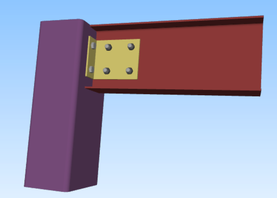
Picture 1. Example of a single angle shear connection One of the most common types of shear connections are the angle/plate connections, which either use an angle bracket or a plate to connect the flange of the parent to the web of the child member. Shear connections do not resist much moment forces as they are allowed some looseness to rotate. If the connections are permitted for rotation, the connections are to resist only shear forces. Therefore, they are designed as shear conenctions. It is one of the main differences between a shear and a moment connection. It is worth noting that welded shear connections resist higher moment loads than bolted ones.
- Angle Connection (Picture 1)
- Single Plate Connection
- WT Connection
- Seated Connection
Steps to Design
In this section, we will discuss about single plate (fin plate) shear connections (Picture 2). Fin plate connections are economical to fabricate and simple to erect. These connections are also popular, as they can be the quickest connections to erect and overcome the problem of shared bolts in two-sided connections.

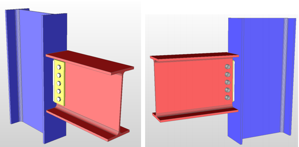
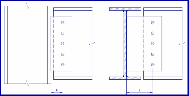
Picture 2. Single plate shear connection The behavior of single plate shear connections is affected by the support conditions, which are idealized as being either flexible or rigid. If the beam is supported by an ideal flexible support such as a beam, which is torsionally unrestrained, then the beam end rotation is entirely accommodated by rotation of the support. However if the beam is supported by a fully rigid support, such as the flange of a W-shape column, then the welded edge of the plate will remain firmly connected with the parent member when loaded by a gravity shear force and rotation is accommodated by deformation within the connection. In the ideal flexible connection, the inflection point is at the face of the supporting member; but in the ideal rigid connection the inflection point moves away from the face of the supporting member. Since “real” supports seldom behave exactly as flexible or rigid connections, redundant design procedures are necessary to provide a safe and efficient design. A typical single plate shear connection is composed of three parts: support, connector and beam. The support may be another beam or girder, a column flange, or a column web (Picture 3). The connector may be either bolted or welded to the support and to the beam. For example, a connector bolted to the support and welded to the beam forms a “bolted-welded” shear connection.

Picture 3. Single plate shear connection beam/column (left) and beam/beam (right) In order to continue, we have to factor limit state considerations. The following list below are the 11 checks (AISC standards) necessary to design a single plate shear connection:
To be able to pass mentioned criteria, we have to stick with general requirements for connecting plates, bolts, and welds.
The minimum bearing capacity is mandatory for all types of fractures of all connection components.
Some of the recommendations (which follows both Australian and American standards) that can be made to make it pass are the following:
- Bolt shear considering bolt eccentricity
- Material bearing strength of the bolt group for both the plate and the beam web
- Plate shear yielding
- Plate shear fracture
- Plate block shear
- Plate flexural yielding due to bending using the plastic section modulus of the plate
- Plate flexural fracture due to bending
- Weld strength for plate to supporting member
- Block shear for coped beams
- Flexural yielding of the coped section of the beam
- Rotational demand of connection for rigid connections only
- Capacity of the bolt group connecting the fin plate to the web of the supported beam
- Strength of the fin plate at the net section under bearing and shear
- Strength of the supported beam at the net section
- Strength of weld connecting fin plate to supporting column
- Local shear check of column web
- Buckling resistance of long fin plates
- Structural integrity
Shear Connection Design (Worked Example)
In this section, we will show an example of single plate shear connection, using SkyCiv Connection Design. The software will show the step-by-step calculations of a shear connection design:

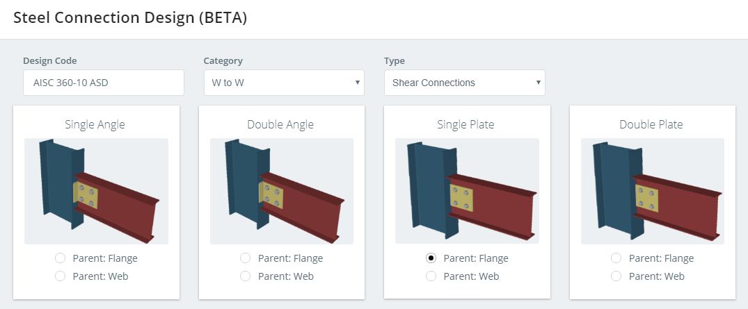
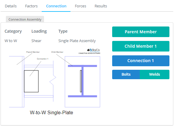
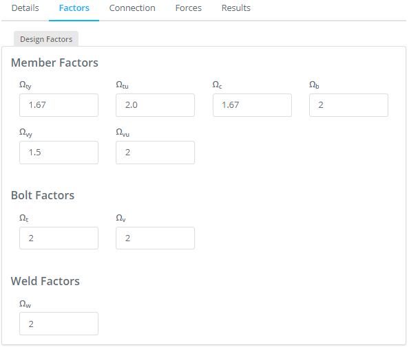
Picture 4. Defining design code, category and type of the shear connection By setting the design factors (member, bolt and weld factors), the next step in the design is with creating a connection assembly (Picture 5) to which the forces can be assigned (Picture 6) and the behaviour of the single plate shear connection can be simulated.


Picture 5.Design factors and connection assembly 
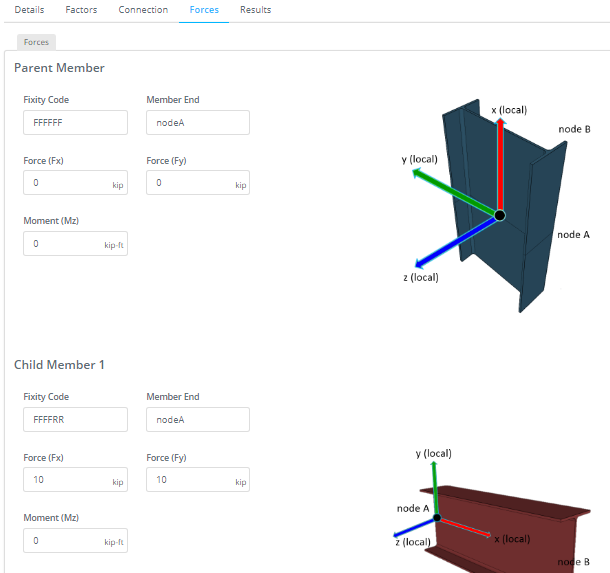
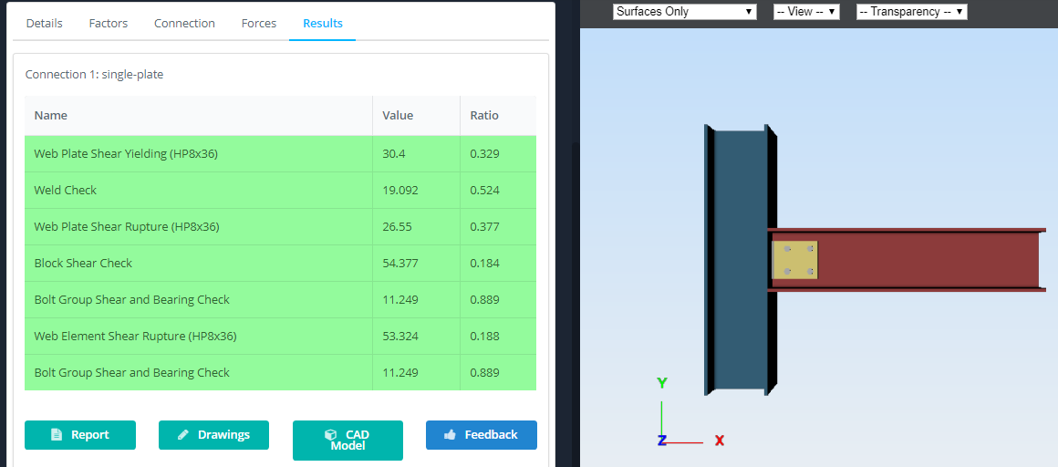
Picture 6. Assigning the forces to a child member After simulating the behaviour of single plate shear connection, the results (Picture 7) will be given in accordance with American Standard AISC 360-10 (14th Edition).

Picture 7. Results The software will also produce a step-by-step guide of the connection shear design calculations for the user's reference. Click the 'Report' icon to view the design output.
For a detailed view of this worked example, feel free to download the detailed worked example of a shear connection design - produced by SkyCiv Connection.