
The Base Plate Connections often serve as the critical interface between the steel structure and the foundation in a number of buildings and structures.
SkyCiv Base Plate and Anchor Design has the following features when designing:
- Intuitive user-interface with easy inputs
- Can solve multiple base in the same project
- Summary table of design check values and ratios
- Detailed, step-by-step calculation report (PDF or HTML download)
SkyCiv Base Plate and Anchor Design currently supports the following capabilities when designing:
- Design checks in compliance with ACI 318 or AISC, Australian Standards and European Standards
- Supports multiple load cases such as Dead, Live, Earthquake, Wind and etc.
- Support Wide Flange and HSS shape type.
- Checks Concentric Compressive Axial Loads.
- Checks Tensile Axial Loads.
- Checks Base Plates with Small Moments
- Checks Base Plates with Large Moments.
- Checks the Design for shear.
- Checks the Design for Anchor Rods (Pullout, Pryout, Sideblow, Breakout).
- Seismic design provision is included.
Below is a list of limitations for SkyCiv Base Plate and Anchor Design :
- The column must be concentric with the base plate and concrete support.
- The base plate must be rectangular.
- The self-weight of the base plate and the anchor bolts are ignored.
Getting Started
- Select starting template and Design Code, illustrated in figure 1 below.
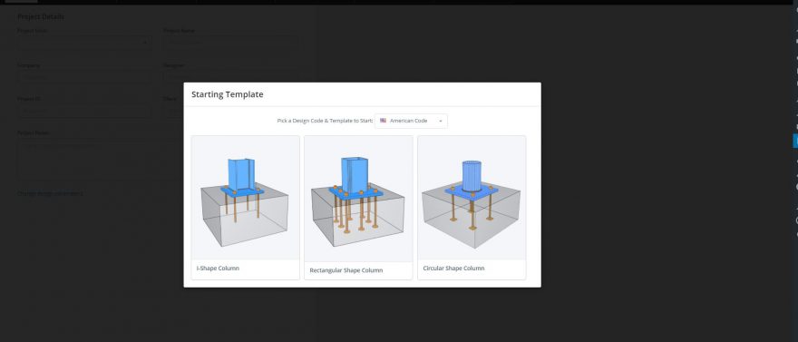
Figure 1 : starting template
2. Under Main Parts tab, user can select (column section and material grades) and define inputs for column, base plate and foundation, illustrated in figure 2 below.
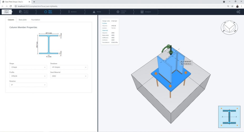
Figure 2: Main parts
3. Under Anchors tab, user can select (material grades and anchor bolt end types) and define inputs for the anchors, illustrated in figure 3 below. The location of the anchors can also be controlled in this part of the UI.
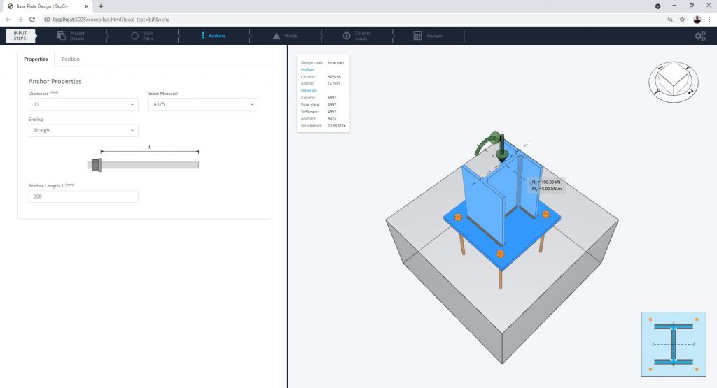
Figure 3: Anchor tabs
4. Under Weld tab, user can select (material grade) and define inputs for the weld, illustrated in figure 4 below.
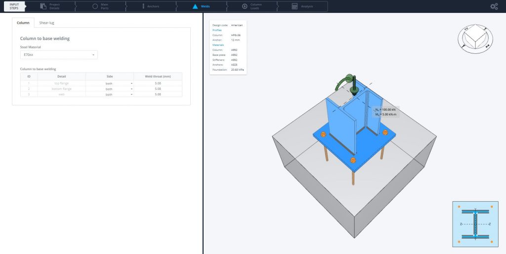
Figure 4: Weld tabs
5. Under Load tab, user can select load static and define inputs for the loads, illustrated in figure 5 below.
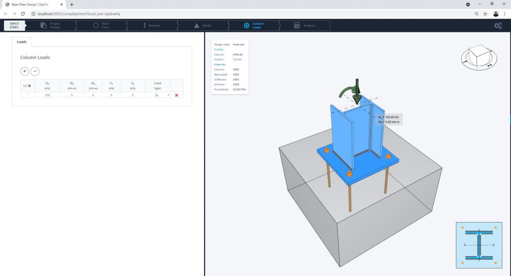
Figure 5: Load tabs
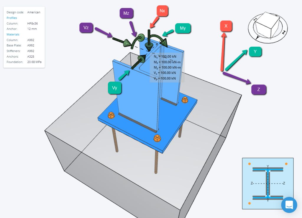
A guide to the load directions are displayed as per below:
6. Click Analysis tab to run the design and see results, illustrated in figure 6 below.
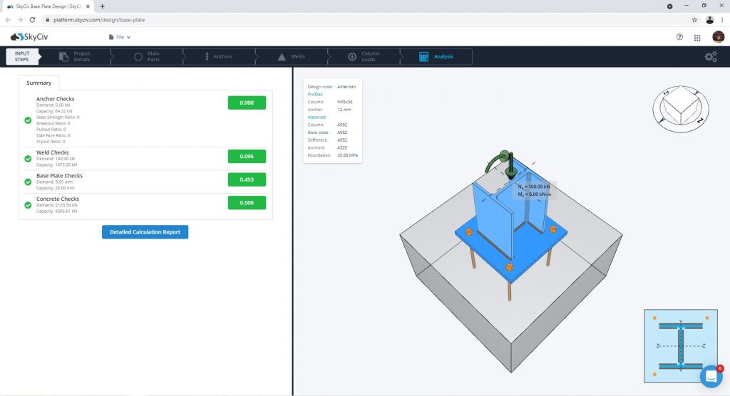
Figure 6: Result tabs
